I’ve switched the blog engine for this site from Ghost to Hugo. All existing links should work, but please leave a comment or email me if anything is broken.
Expect some new posts soon, starting with a look at the PLUS language.
We’ll now look at GPSS, a simulation language included in MTS. Due to the specialized nature of this language I’ll only devote a single post to it - but it’s a very interesting language, so let’s dive in!
General Purpose Simulation System
GPSS, General Purpose Simulation System, is a language to simulate discrete systems to see how they perform over time. Sample uses include modeling a checkout at a supermarket or how a manufacturing assembly line will work. The programmer defines how transactions are created (eg a shopper), what resources are available (eg how many checkouts and how long they take to process) and how transactions move through the system. When run, it simulates a clock and processes these transactions, giving output that shows the performance of the system, eg how long on average a shopper had to queue for and how busy the checkouts where during a simulated day.
GPSS on MTS
GPSS was created by Geoffrey Gordon in around 1961 and was originally implemented on IBM systems. The version we have on MTS, GPSS/360, is available as *GPSS. Later versions of GPSS such as GPSS/H did run on MTS and may be available in future distributions (see this message at the MTS Archive).
Prerequisites
No special installation instructions to get this language running - just do the standard D6.0 setup as described in this guide and then sign on as a regular user such as ST01.
We are modeling a barber shop with the following qualities:
The shop contains one barber and one barber’s chair, open for eight hours in a day.
Customers arrive on average every 18 minutes, with the arrival time varying between 12 and 24 minutes.
If the barber is busy, the customer will wait in a queue.
Once the barber is free, the next customer will have a haircut.
Each haircut takes between 12 and 18 minutes, with the average being 15 minutes.
Once the haircut is done, the customer will leave the shop.
We want to answer these questions:
How utilised is the barber through the day?
How long does the queue get?
On average, how long does a customer have to wait.
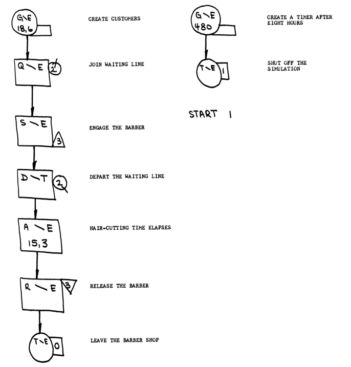
The manual uses a block diagram notation to show how this is simulated - you can see this at the top of this page. The equivalent GPSS program looks like this:
       SIMULATE
       GENERATE   18,6       CREATE CUSTOMERS
       QUEUE      2          CUSTOMERS QUEUE UP IF NECESSARY
       SEIZE      3          ENGAGE THE BARBER WHEN HE BECOMES AVAILABLE
       DEPART     2          CUSTOMER LEAVES THE QUEUE
       ADVANCE    15,3       CUSTOMER GETS HIS HAIR CUT
       RELEASE    3          RELEASE THE BARBER
       TERMINATE  0          LEAVE THE BARBER SHOP
       GENERATE   480        GENERATE A TIMER AFTER 8 HOURS OF SIMULATED TIME
       *
       TERMINATE  1          SHUT OFF THE RUN
       START      1          CARRY OUT THE SIMULATION
       END                   RETURN CONTROL TO THE OPERATING SYSTEM
The text at the end of each line is a comment; starting a line with * means the rest of the line is a comment; we use this just to separate the two parts of the program as explained below.
GPSS works in units rather than absolute time, so we shall say that 1 time unit is equal to 1 minute. Programs can be read from top to bottom: the simulator runs by advancing the clock one time unit and working out where transactions are in the system.
The first line, SIMULATE, denotes the start of the code.
GENERATE 18,6 means generate a transaction - a barber shop customer - every 18 minutes ± 6 minutes.
QUEUE 2 defines a queue with ID 2, denoting the queue where customers will wait.
SEIZE 3 defines a facility with ID 3. The facility is the barber and this line means if the barber is free, the next customer occupies the barber until released.
DEPART 2 says that the customer leaves the queue when occupying the barber.
ADVANCE 15,3 means that transactions in this state only move on after 15 minutes ± 3 minutes - modeling the time taken for a haircut. After that RELEASE 3 shows that the customer no longer occupies the barber and TERMINATE 0 ends the transaction, showing that the customer has left the shop.
That is all that is needed for the basic simulation, but if run like this it would never stop, as we have not modeled the 8 hour period the shop is open.
To do this we generate a new transaction with GENERATE 480, which means generate a transaction after 480 minutes, ie 8 hours. The next line, TERMINATE 1, stops the simulation after this transaction is generated.
With that done, the last two lines start the simulator and returns control to MTS when it is done.
Running the program using *GPSS
*GPSS takes the input file on scards and outputs to *sink* by default. Assuming the simulation defined above is stored in barb1.gpss, this is how it would look:
We start off with the program listing, where GPSS denotes which lines are components of the simulation with a block ID. So GENERATE 18,6 is on line 3 but is block 1.
$run *gpss scards=barb1.gpss
Execution begins   16:07:50


     GPSS/360    VERSION 1  MODIFICATION LEVEL 4    MTS MODEL (AN104)    16:07:50  11-03-17

     LINE# CARD#  BLOCK#  *LOC   OPERATION  A,B,C,D,E,F,G    COMMENTS

     1.000     1                 SIMULATE
     2.000     2          * BARBER SHOP SIMULATOR
     3.000     3  1              GENERATE   18,6       CREATE CUSTOMERS
     4.000     4  2              QUEUE      2          CUSTOMERS QUEUE UP IF NECESSARY
     5.000     5  3              SEIZE      3          ENGAGE THE BARBER WHEN HE BECOMES AVAILABLE
     6.000     6  4              DEPART     2          CUSTOMER LEAVES THE QUEUE
     7.000     7  5              ADVANCE    15,3       CUSTOMER GETS HIS HAIR CUT
     8.000     8  6              RELEASE    3          RELEASE THE BARBER
     9.000     9  7              TERMINATE  0          LEAVE THE BARBER SHOP
    10.000    10          *
    11.000    11  8              GENERATE   480        GENERATE A TIMER AFTER 8 HOURS OF SIMULATED
    12.000    12  9              TERMINATE  1          SHUT OFF THE RUN
    13.000    13                 START      1          CARRY OUT THE SIMULATION
    14.000    14                 END                   RETURN CONTROL TO THE OPERATING SYSTEM
Next, GPSS shows how many transactions were in each block at the end of the simulation and in total.
RELATIVE CLOCK          480  ABSOLUTE CLOCK          480
 BLOCK COUNTS
 BLOCK CURRENT    TOTAL    BLOCK CURRENT    TOTAL    BLOCK CURRENT    TOTAL    BLOCK CURRENT    TOTAL    BLOCK CURRENT    TOTAL
     1      0        27
     2      0        27
     3      0        27
     4      0        27
     5      1        27
     6      0        26
     7      0        26
     8      0         1
     9      0         1
We can see that 27 transactions were generated in block 1, which means 27 customers entered the shop during the day. Blocks 8 and 9 had 1 transaction, which is expected as this was the timing transaction. Why does block 5 have one current transaction while all others are zero? Block 5 is the ADVANCE statement, representing the haircut, and this means one customer was in the chair at the end of the simulated day.
GPSS then prints out statistics on the facility, or the barber in our simulation:
 FACILITY        AVERAGE         NUMBER        AVERAGE          SEIZING    PREEMPTING
               UTILIZATION      ENTRIES       TIME/TRAN        TRANS. NO.  TRANS. NO.
        3          .816              27          14.518            1
So our barber was used 81.6% of the day, and each haircut took on average 14.518 minutes.
We then see details of the queue:
 QUEUE      MAXIMUM     AVERAGE     TOTAL       ZERO     PERCENT      AVERAGE      $AVERAGE      TABLE     CURRENT
           CONTENTS    CONTENTS    ENTRIES    ENTRIES     ZEROS     TIME/TRANS    TIME/TRANS    NUMBER    CONTENTS
     2            1        .085        27         16       59.2         1.518         3.727
  $AVERAGE TIME/TRANS = AVERAGE TIME/TRANS EXCLUDING ZERO ENTRIES
MAXIMUM CONTENTS means there was never more than one customer in the queue. Although 27 customers entered the queue, 16 were zero entries - this means they entered and immediately left the queue, ie the barber was unoccupied when they entered the shop. For those that did wait in the queue, the average wait was 3.727 minutes; including the zero entries, the average time for all customers to wait was 1.518 minutes.
Finally, GPSS prints usage statistics and exits:
CPU TIME USED (SECONDS)

  ASSEMBLY:      .001

TOTAL BLOCK EXECUTIONS:     189

MSEC/BLOCK AVG CPU TIME:   .003

Execution terminated   16:07:50  T=0.004  RC=0  $0.00
It’s interesting to compare this to the printout in the manual from 1968. Our run took 0.004 seconds of CPU time, compared to 4.5 seconds then. And of course our run had no charge, whereas the run from 1968 would have cost 41¢.
The manual goes on to refine the model further - dealing with the customer left in the chair, and simulating more complex scenarios - but we will leave it at that for now.
Further information
Full source code for the program described above can be found on github.
Modern implementations of GPSS on Windows are sold by Wolverine Software and Minuteman Software; both offer a free student version with limited model sizes.
Several other simulation languages have been created, eg Simula; a list of languages for discrete event simulations can be found at Wikipedia.
In the last part of this series we’ll write a real program in assembly language.
The problem
We’ll implement the Caesar cipher from Rosetta Code. This is a very simple cipher where the key indicates how much to rotate the alphabet by. So with a key of 2, ABC XYZ would be encoded as CDE ZAB. The solution should handle both encoding and decoding; decoding simply needs a rotation by the key in the opposite direction.
Finding a algorithm
This appears quite simple at first. Take each letter’s code, add the key and return the new letter, accounting for wrap around at Z.
However, this assumes that letters are coded in a contiguous manner, as they are in ASCII. The System/360 uses EBCDIC, and if you look at the code chart on Wikipedia you’ll see that A, B, C, … I are contiguous, but there’s then a gap of 7 characters before J, K, … R, then another gap and so on.
Now you could account for this but it would be very fiddly in assembler. Instead, let’s try another way.
What if we transformed A, B, C into offsets 0, 1, 2. Next, add the key and use that as an index into a table of letters repeated to allow wrap around. This should work, but how to implement it?
Turning letters into offsets
The first step is turning A, B, C into 0, 1, 2. There’s a useful opcode called TR that can help us here.
TR WORK,OFFSETS
This will take each byte in WORK, look up its position in OFFSETS and update WORK to be the value found there. So if WORK[0] is ‘A’ (193 in EBCDIC), find the value at OFFSETS[193], which we could arrange to be 0, and then update WORK[0] to be that value.
For this to work, we need to set up OFFSETS correctly. This can be done with some trickery with DC:
OFFSETS  DC    256AL1(*-OFFSETS)
         ORG   OFFSETS+C'A'
         DC    X'000102030405060708'
         ORG   OFFSETS+C'J'
         DC    X'090A0B0C0D0E0F1011'
         ORG   OFFSETS+C'S'
         DC    X'1213141516171819'
         ORG
The first line defines
an address A, 32 bits
converted to length of 1 byte with L1
repeated 256 times
with value at each time *-OFFSETS, where * is the current location
The effect of this is to create a block of memory 256 bytes long with values 0, 1, 2, …, 255.
The next line uses ORG to set the location counter to OFFSETS+C'A', ie the position where A would be in the EBCDIC table. We then overwrite a part of the 256 byte block with the bytes 00, 01, 02, …, 09, creating the offset to replace letters A - I with. We do this again for the letter run starting with J and S.
Turning offsets into letters
To go the other way, ie change an offset like 0, 1 into letters A, B, we define a block of letters:
FLAT0    DC    C'ABCDEFGHIJKLMNOPQRSTUVWXYZ'
FLAT     DC    C'ABCDEFGHIJKLMNOPQRSTUVWXYZ'
FLAT1    DC    C'ABCDEFGHIJKLMNOPQRSTUVWXYZ'
We do this contiguously three times to allow for forward and reverse rotations with the key, so FLAT+1 gives us B and FLAT-1 gives us Z. Doing it this way allows easy access; we could just use one block of letters and deal with rotated offsets past the ends with extra logic, but I don’t mind giving up memory for ease of access here.
Byte access to memory
The final piece we need is a way to access bytes in memory. For this we can read a byte (insert a character) with IC, eg:
IC 4,WORK(1)
This will set register 4 to the value in memory at the byte addressed by WORK + 1.
To store a character back into memory, STC can be used in a similar way.
The ROT subroutine
With this we have enough to define the subroutine to rotate a message by a given key:
* ROT subroutines implements Caesar cipher message letter rotation
*
* Parameters:
* R0 - Key for cipher. 1 to 25 to encode, -1 to -25 to decode
* WORK - Buffer containing message to encode/decode of length MSGLEN
*        Will be overwritten with encoded/decoded message
* Return values:
* None
*
         ENTRY ROT                Subroutine entry for ROT
ROT      ENTER 12,SA=RSAVE        Use R12 for base address
         TR    WORK,OFFSETS       Translate letters into offsets
         L     1,=F'0'            Loop start value
         L     2,=F'1'            Loop increment
         LA    3,L'MESSAGE-1      Loop final value
LOOP     IC    4,WORK(1)          Get message byte at loop index
         C     4,MAXOFF           Is it an offset?
         BH    STORE              If no, don't change it
         LA    10,FLAT            Load base of flat letter array
         AR    10,0               Add the key displacement
         IC    4,0(4,10)          Fetch into R4 FLAT+KEY+OFFSET
STORE    STC   4,WORK(1)          Store char back into work
         BXLE  1,2,LOOP           Loop if index <= final
         EXIT
We use a predefined area of memory WORK to do the transformation rather than passing in an address, again just for convenience.
Note the explicit use of addressing in IC 4,0(4,10). The second parameter means use register 10 as the base address and add the contents of register 4 to the displacement 0.
One other observation is that the BXLE loop is only needed as we want to skip over non-alphabetic characters in the message. If we knew the message can only contain A-Z, we could do something like TR WORK,FLAT+KEY to do the whole message in one go.
Putting it together
We need a couple more things: first the definition of the message and key, and working areas:
*
* Inputs to program
*
MESSAGE  DC    C'THE FIVE BOXING WIZARDS JUMP QUICKLY!'
KEY      DC    F'7'
*
* Working buffers
*
ENC      DS    CL(L'MESSAGE)
DEC      DS    CL(L'MESSAGE)
WORK     DS    CL(L'MESSAGE)
RSAVE    DS    18F                Save area
*
* Constants
*
MAXOFF   DC    F'25'
And finally, a test call to encode and decode the message, using MVC to copy a block of memory to another location:
CAESAR   START 0                  Program at relative address 0
         USING CAESAR,12          R12 will contain program addr
         LR    12,15              Load R12 with absolute addr
*
* Encode the plain-text message to ENC
         MVC   WORK,MESSAGE       Copy message to WORK
         L     0,KEY              Set key
         CALL  ROT                Encode the message
         MVC   ENC,WORK           Copy encoded message to ENC
*
* Decode the encoded message to DEC
         L     0,KEY              Set the key
         LNR   0,0                Negate the key for decoding
         CALL  ROT                Decode the message
         MVC   DEC,WORK           Copy decoded message to DEC
*
* Print results and exit
         SPRINT MESSAGE           Print the original message
         SPRINT ENC               Print the decoded message
         SPRINT DEC               Print the encoded message
         SYSTEM                   Exit program
Assembling and running the program
$ run *asmg scards=caesar.asm spunch=-load sercom=*sink* par=test

...

$run -load
Execution begins   18:29:02
THE FIVE BOXING WIZARDS JUMP QUICKLY!
AOL MPCL IVEPUN DPGHYKZ QBTW XBPJRSF!
THE FIVE BOXING WIZARDS JUMP QUICKLY!
Execution terminated   18:29:02  T=0  RC=0  $0.00
Thoughts on the program and assembly
I think that was the hardest program to write of all the languages so far. The documentation is very good, but terse - I can imagine reading the Principle of Operation several times would pay off greatly. Also having to flip between Principles, the Assembler F reference and MTS documentation rather than having everything in one place was tough. But it was very rewarding to get the program running.
I’m not entirely happy with the final design I came up with - I’m sure there’s an easier or more efficient way. I’d love to hear from experience System/360 assembly language programmers out there how you’d implement this.
Further information
Full source code for this program can be found on github.
In the previous post we got a simple assembly language program running. Let’s now look in more detail at how to program in System/360 assembly language. Although a lot of this material is common across other System/360 operating systems and assemblers, it does contain specifics for MTS and Assembler G.
This only covers the surface of the subject: see the end of this post for some of what was missed and how to find more information.
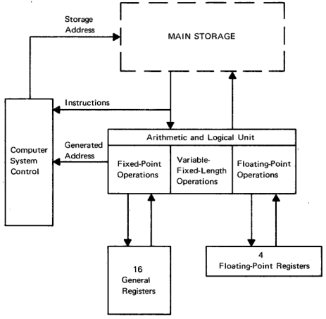
Architecture overview
The IBM System/360 and its derivatives has the following basic architecture.
32 bit words, with access to 16 bit halfwords and 8 bit bytes.
Big-endian, using 2’s compliment for signed values.
16 general purpose 32 bit registers, 4 64 bit floating point registers, plus support for BCD arithmetic.
24 bit memory addressing.
A 64 bit program status word (PSW), which contains the address of the current instruction being executed, condition codes and interrupt masks.
Most System/360 models did not support virtual memory, but the one used for MTS did.
Assembly language
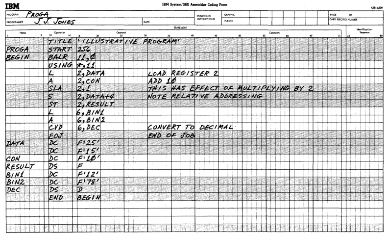
The assembly language defined by IBM is line based, with the following components separated by whitespace:
An optional label, which must start in column 1 if present.
An opcode, assembler directive or macro indicating the operation to perform.
An optional set of operands separated by commas.
An optional comment.
An optional identification sequence, in columns 73-80, commonly used to number each statement.
Apart from the first and last element, which columns are used is not important, but by convention they are lined up.
An example
Let’s look at lines from the ‘Hello, world’ example from the last post to illustrate these features.
This line loads registers 12 with the contents of register 15.
LR 12,15 LOAD R12 WITH ABSOLUTE ADDR
The next line loads register 3 with the value found at the address with label RUNS.
L 3,RUNS R3 COUNTS DOWN NUMBER OF RUNS
Looking at the line labeled RUNS, we can see the value pointed to defined as a constant using the assembler directive DC. Constants of different types are represented with quotes, so F'5' means a fullword (32 bit quantity) with a value of 5. X'BEEF0' would be a 20 bit value composed of the 5 hex digits BEEF0 each taking up 4 bits.
RUNS DC F'5' NUMBER OF RUNS TO MAKE
DC stands for data constant, and arranges a value to be placed at a location in memory after the previous line. DS can be used to arrange data storage, allowing the program to write values back to memory.
Finally, here is a macro call, which will take the string as parameter and arrange a subroutine call to the SPRINT service provided by MTS:
LOOP SPRINT 'Hello, world!' PRINT THE MESSAGE
Operation formats, base registers and addressing
Next let’s see how the assembler constructs machine instructions from parts of this program. The listing sent to sprint when running the assembler contains a dump of memory locations and assembled code for each line. For example, here’s the line where the RUNS constant is stored (I’ve omitted some columns from the listing for clarity). Here we can see the fullword quantity 5 being stored at address 3c.
LOC    OBJECT CODE  SOURCE STATEMENT
00003C 00000005     RUNS     DC      F'5'
The load statement L 3,RUNS looks like this:
LOC    OBJECT CODE   SOURCE STATEMENT
000002 5830 C03C     L       3,RUNS
Breaking down the object code:
Opcodes on System/360 are a single byte: here 58 is the opcode for L, load.
The next four bits, 3, represents the register to load into.
The next four bits, 0 is the index register
The next four bits, C, is the base register.
The final 12 bits, 03C, is the displacement.
The address to load from is base register + index register + displacement. In this example, the index register is 0 which indicates it is not being used, so at run time the system will find the value at offset 3c from whatever is in the base register.
The base register is present in nearly all addressing operations and ensures that System/360 is relocatable: at run time, the start of this piece of code is loaded into memory somewhere and a register is set to that address so all further address arithmetic can use it.
In our example, this was set up with assembler directives at the start of the program:
HELLO    START   0
         USING   HELLO,12
         LR      12,15
Here, START 0 means the program will be placed at offset 0 in the block of memory being composed. USING HELLO,12 states that register 12 (C) will be the base register. Finally, LR 12,15 loads register 12 with the contents of register 15: this is part of the calling convention for MTS, so when the program starts it knows it can find its own start address in register 15. Using USING allows the assembler to take care of the base register for you, but you can also specify it and the index register directly.
This sequence of opcode and operands is called RX format. Other opcodes use other formats; for example, the LR 12,15 is in RR format, where the one byte opcode is followed by two 4 bit register operands. Other formats can take an immediate value and an address, or two addresses.
Loads and stores and binary arithmetic
Armed with this knowledge, it’s fairly easy to understand the basic instruction set described in the IBM System/360 Principles of Operation manual. Let’s look at the load instructions for example:
Name
Mnemonic
Type
Load
LR
RR
Load
L
RX
Load Halfword
LH
RX
Load and Test
LTR
RX
Load Complement
LCR
RX
Load Positive
LPR
RX
Load Negative
LNR
RX
Load Multiple
LM
RS
We’ve seen L and LR already. LH loads a halfword (16 bit) quantity from the given address, sign extending it to a fullword. LTR will load a value and set condition codes, which will look at in the next section. LCR will load a value and toggle the sign; LPR and LNR will load and force positive or negative.
LM, load multiple, uses a format we’ve not seen so far, RS. This format is composed like this:
One byte opcode
Four bits register R1
Four bits register R3
Four bits register B2
12 bits displacement
For LM, data is loaded from the address computed from the base register B2 + displacement into a sequence of registers starting at R1 and ending at R3. So the instruction
LM 3,5,12,0
will load up the registers R3, R4 and R5 with data from the memory address in base register 12 + 0 offset, reading 3 fullword values in sequence.
For stores, we have ST for store fullword quantity in a register to memory, STH for storing a halfword and SM for storing multiple registers to a sequence in memory.
Addition opcodes are A and AR for add memory to register and add register to register. AH to add halfwords and AL/ALR to add ignoring the sign bit. Subtraction is orthogonal.
Multiplication and division result in a 64 bit value so as not to lose precision. The input register must have an even number and the results are stored in that plus the next sequential register, so
M 2,LABEL
will multiply the value of register 2 and the value found at LABEL, then store the results in registers 2 and 3.
The PSW and branches
The PSW, or program status word, is a doubleword that defines the current state of the processor. It includes fields that indicate interrupt masks, state (eg problem state), condition codes and the current instruction address.
The condition code occupies bits 34 and 35. They have the following meaning:
00 - zero
01 - negative
10 - positive
11 - carry/overflow
The condition code is set after many operations, for example add, subtract or load and test.
The branch on condition opcode can be used to branch based on its value. This comes in two formats, a RR instruction BCR where if the branch is made, the address is taken from one register, or BC which uses the base+index+displacement system.
Whether to take the branch or not is determine by a four bit mask. A mask value of 8 means branch if condition code 00 is set, mask value 4 for 01 etc. These can be added together, so a mask value of 12 means branch on either condition code 00 or 01 (zero or negative). If all four mask bits are set, the branch is unconditional, if unset, then the instruction is a no-op.
As specifying the mask each time can be tedious, the assembler provides directives for common cases such as branch if zero or branch if positive. We can see this in the ‘hello, world’ program:
         S       3,DECR            DECREMENT R3
         BP      LOOP              IF R3 POSITIVE, LOOP AGAIN
BP stands for branch if positive, and will test the condition code from the previous S subtract: if the value is positive, then jump to address labeled as LOOP.
Internally, the assembler turns BP LOOP into BC 2,LOOP(0,12), using mask 2 = condition code 10 and if positive branching to the address given by the base register 12 + LOOP.
There are also higher level branch instructions suitable for loops, for example:
BXLE 1,2,LABEL
BXLE stands for branch on index low or equal. In this example, register 1 is incremented by the value of register 2. If register 1 is less than equal to the value in register 3, then the branch is taken.
Subroutines
Supporting subroutines or functions requires a facility to pass in parameters, jump to the called code, do an operation, and return to the calling code with any results. On most modern systems this is done via a stack, but you may have noticed this was not part of the architecture overview above, so how is this done?
The answer is that a combination of a save area in memory is used to store data plus a calling convention so the caller and callee can exchange information via registers. The actual change in location address is done by a branch when this is set up. The calling convention used is up to the programmer, but in practice IBM defines a standard calling convention so that code in different languages can operate together.
(24 March 2018: See the comment below from Jeff Ogden for more details on the calling convention.)
Register 1 points to an address where a list of parameters for the called program is stored..
Register 13 points to a save area, described below.
Register 14 points to the next instruction in the calling program that the called program should return to after execution is done.
Register 15 points to the entry point of the called program.
The save area is a portion of memory with a specific format, owned by the calling program where the called program can save registers and other data. For example, word 6 is used to store the contents of register 0. It is the responsibility of the called program to save data in the save area and restore it before returning execution to the caller.
A byproduct of this is that recursion is not freely available like on stack based architectures, as there is a single save area per program call, multiple calls would overwrite this area. Special code is needed to dynamically allocate save areas if recursion is required.
Macros and calling the MTS system
Setting up these subroutine calls by hand would be tedious. Luckily, the assembler includes a powerful macro facility that helps abstract these away, and macros have been defined as follows:
CALL to pass parameters to a subroutine
ENTER to start a subroutine and set up registers and save area
EXIT to restore saved values and pass back a result code.
Macros are also defined for MTS system facilities. We saw this in the ‘hello world’ program in two places:
LOOP     SPRINT 'Hello, world!'    PRINT THE MESSAGE
...
         SYSTEM                    EXIT PROGRAM
We can see how these were assembled by looking at the listing file. The SYSTEM call is easiest as it takes and returns no parameters:
L     15,=V(SYSTEM)
BR    15
Register 15 is loaded with the address of the SYSTEM subroutine (which is determined at link time) and an unconditional branch is made.
The SPRINT call is more complex:
L     15,=V(SPRINT)                SUBROUTINE TO DO I/O
BAL   1,*+18+((L'###1+1)/2*2)      AROUND CONSTANTS
DC    A(*+14)                      DATA ADDRESS
DC    A(*+8)                       LENGTH
DC    A(0)                         NO MODIFIERS SPECIFIED
DC    Y(L'###1)                    LENGTH
DC    C'Hello, world!'
BALR  14,15                        BRANCH TO SUBROUTINE
The L sets up the subroutine address in register 15. A parameter list is defined with the DCs; the BAL puts the address of this in register 1 and jumps over the constants.. Finally, BALR is used to jump to the address stored in register 15, storing the current address (and other bits from the PSW) in register 14.
Other features
The information presented above should be enough to get started with assembler programming on MTS. We have not covered a number of other features supported by the system, including
Decimal and floating point arithmetic
Logical operations like AND
Byte access and character operations
I/O operations and channels
Other parts of the PSW and their use in system programs.
Further information
See the end of the last post for links to documentation to find out more about assembly language.
In the next post we’ll write a complete program in assembly.
Sample assembly language program form, from ‘A Programmer’s Introduction to IBM System/360 Assembler Language
After the heights of APL, let’s turn to the lowest level language possible: System/360 assembly language.
System/360 Assembly Language
MTS runs on the IBM System/360, designed from scratch by IBM in the early 1960s as a unified successor to a number of different architectures. System programmers, and application programmers looking for maximum performance used assembler to write code as close to the bare metal as possible.
As the System/360 was a new design, the architecture is clean and fairly simple. It’s a 32 bit architecture with 24 bit addresses, 16 full word registers and 4 64 bit floating point registers. Binary Coded Decimal (BCD) arithmetic and I/O operations are also supported.
Assemblers on MTS
MTS ran originally on a System/360-67, and later on 370 and Amdahl CPUs which provided extensions to the basic instruction set that we will not consider here.
The main assembler available to us today is Assembler G (*ASMG). This is a basic assembler, derived from Assembler F provided by IBM for OS/360 with extensions by the University of Waterloo for improved performance.
At the time of MTS D6, the most common assembler in use was Assembler H. This has a considerable number of improvements to the assembly language supported in Assembler G; however, this is not available in the MTS distribution due to copyright reasons.
ASSIST, Assembler System for Student Instruction & Systems Teaching, was an assembler and emulator used by students to learn assembly. As it emulates the underlying machine it can provide additional debug information and run time control, at the expense of performance. It is available on the MTS distribution as *ASSIST. Finally, *ASMT is a specialised assembler compatible with features on IBM’s time sharing system TSS. We will not consider either of these further in these blog posts.
Prerequisites
No special installation instructions to get this language running - just do the standard D6.0 setup as described in this guide and then sign on as a regular user such as ST01.
Running a program using *ASMG
*ASMG will take a file of assembly language instructions from scards and write output to spunch. A program listing can be sent to sprint and errors to sercom if these are set on the command line. Extra parameters can be set with par, for example par=test will add debugging information to the object file.
Linking is done at run time by MTS, so if you are just using the system libraries the object file can be run directly with $run.
Hello world
Let’s see how to run a simple program to print ‘Hello, world!’ five times using assembly language.
The source file (with line numbers) looks like this:
# list hello.asm
       1     HELLO    START   0                 PROGRAM AT RELATIVE ADDRESS 0
       2              USING   HELLO,12          R12 WILL CONTAIN PROGRAM ADDR
       3              LR      12,15             LOAD R12 WITH ABSOLUTE ADDR
       4              L       3,RUNS            R3 COUNTS DOWN NUMBER OF RUNS
       5     LOOP     SPRINT 'Hello, world!'    PRINT THE MESSAGE
       6              S       3,DECR            DECREMENT R3
       7              BP      LOOP              IF R3 POSITIVE, LOOP AGAIN
       8              SYSTEM                    EXIT PROGRAM
       9     RUNS     DC      F'5'              NUMBER OF RUNS TO MAKE
      10     DECR     DC      F'1'              DECREMENT FOR LOOP
      11              END     HELLO             END OF CODE
Here’s how to run the assembler. We send errors to *sink* so they are displayed immediately and a full program listing to -hello.l.
# $run *asmg scards=hello.asm spunch=-load sercom=*sink* sprint=-hello.l par=test
. *** *ASMG has been changed to use *ASMGSYSMAC for the default macro
. *** library instead of *SYSMAC.  It will no longer work with *SYSMAC.
# Execution begins   18:19:08

  ASSEMBLER (G) DONE           18:19:08   30 SEP 17

  NO STATEMENTS FLAGGED IN THIS ASSEMBLY
# Execution terminated   18:19:08  T=0.091
We can ignore the *ASMG has been changed... message; NO STATEMENTS FLAGGED means that it worked OK.
MTS Volume 14: 360/370 Assemblers in MTS details the differences between Assembler G and Assembler H, macro libraries, structured programming macros and the ASSIST assembler.