System/360 Assembly Language - Features
In the previous post we got a simple assembly language program running. Let’s now look in more detail at how to program in System/360 assembly language. Although a lot of this material is common across other System/360 operating systems and assemblers, it does contain specifics for MTS and Assembler G.
This only covers the surface of the subject: see the end of this post for some of what was missed and how to find more information.
Architecture overview
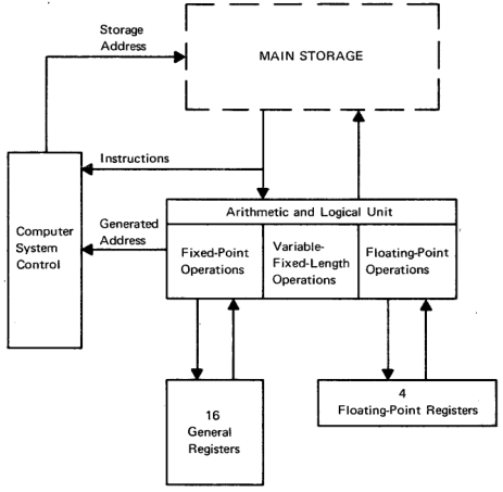
The IBM System/360 and its derivatives has the following basic architecture.
- 32 bit words, with access to 16 bit halfwords and 8 bit bytes.
- Big-endian, using 2’s compliment for signed values.
- 16 general purpose 32 bit registers, 4 64 bit floating point registers, plus support for BCD arithmetic.
- 24 bit memory addressing.
- A 64 bit program status word (PSW), which contains the address of the current instruction being executed, condition codes and interrupt masks.
Most System/360 models did not support virtual memory, but the one used for MTS did.
Assembly language
The assembly language defined by IBM is line based, with the following components separated by whitespace:
- An optional label, which must start in column 1 if present.
- An opcode, assembler directive or macro indicating the operation to perform.
- An optional set of operands separated by commas.
- An optional comment.
- An optional identification sequence, in columns 73-80, commonly used to number each statement.
Apart from the first and last element, which columns are used is not important, but by convention they are lined up.
An example
Let’s look at lines from the ‘Hello, world’ example from the last post to illustrate these features.
This line loads registers 12 with the contents of register 15.
LR 12,15 LOAD R12 WITH ABSOLUTE ADDR
The next line loads register 3 with the value found at the address with label RUNS.
L 3,RUNS R3 COUNTS DOWN NUMBER OF RUNS
Looking at the line labeled RUNS, we can see the value pointed to defined as a constant using the assembler directive DC. Constants of different types are represented with quotes, so F'5' means a fullword (32 bit quantity) with a value of 5. X'BEEF0' would be a 20 bit value composed of the 5 hex digits BEEF0 each taking up 4 bits.
RUNS DC F'5' NUMBER OF RUNS TO MAKE
DC stands for data constant, and arranges a value to be placed at a location in memory after the previous line. DS can be used to arrange data storage, allowing the program to write values back to memory.
Finally, here is a macro call, which will take the string as parameter and arrange a subroutine call to the SPRINT service provided by MTS:
LOOP SPRINT 'Hello, world!' PRINT THE MESSAGE
Operation formats, base registers and addressing
Next let’s see how the assembler constructs machine instructions from parts of this program. The listing sent to sprint when running the assembler contains a dump of memory locations and assembled code for each line. For example, here’s the line where the RUNS constant is stored (I’ve omitted some columns from the listing for clarity). Here we can see the fullword quantity 5 being stored at address 3c.
LOC    OBJECT CODE  SOURCE STATEMENT
00003C 00000005     RUNS     DC      F'5'
The load statement L 3,RUNS looks like this:
LOC    OBJECT CODE   SOURCE STATEMENT
000002 5830 C03C     L       3,RUNS
Breaking down the object code:
- Opcodes on System/360 are a single byte: here
58is the opcode forL, load. - The next four bits,
3, represents the register to load into. - The next four bits,
0is the index register - The next four bits,
C, is the base register. - The final 12 bits,
03C, is the displacement.
The address to load from is base register + index register + displacement. In this example, the index register is 0 which indicates it is not being used, so at run time the system will find the value at offset 3c from whatever is in the base register.
The base register is present in nearly all addressing operations and ensures that System/360 is relocatable: at run time, the start of this piece of code is loaded into memory somewhere and a register is set to that address so all further address arithmetic can use it.
In our example, this was set up with assembler directives at the start of the program:
HELLO    START   0
         USING   HELLO,12
         LR      12,15
Here, START 0 means the program will be placed at offset 0 in the block of memory being composed. USING HELLO,12 states that register 12 (C) will be the base register. Finally, LR 12,15 loads register 12 with the contents of register 15: this is part of the calling convention for MTS, so when the program starts it knows it can find its own start address in register 15. Using USING allows the assembler to take care of the base register for you, but you can also specify it and the index register directly.
This sequence of opcode and operands is called RX format. Other opcodes use other formats; for example, the LR 12,15 is in RR format, where the one byte opcode is followed by two 4 bit register operands. Other formats can take an immediate value and an address, or two addresses.
Loads and stores and binary arithmetic
Armed with this knowledge, it’s fairly easy to understand the basic instruction set described in the IBM System/360 Principles of Operation manual. Let’s look at the load instructions for example:
| Name | Mnemonic | Type |
|---|---|---|
| Load | LR | RR |
| Load | L | RX |
| Load Halfword | LH | RX |
| Load and Test | LTR | RX |
| Load Complement | LCR | RX |
| Load Positive | LPR | RX |
| Load Negative | LNR | RX |
| Load Multiple | LM | RS |
We’ve seen L and LR already. LH loads a halfword (16 bit) quantity from the given address, sign extending it to a fullword. LTR will load a value and set condition codes, which will look at in the next section. LCR will load a value and toggle the sign; LPR and LNR will load and force positive or negative.
LM, load multiple, uses a format we’ve not seen so far, RS. This format is composed like this:
- One byte opcode
- Four bits register R1
- Four bits register R3
- Four bits register B2
- 12 bits displacement
For LM, data is loaded from the address computed from the base register B2 + displacement into a sequence of registers starting at R1 and ending at R3. So the instruction
LM 3,5,12,0
will load up the registers R3, R4 and R5 with data from the memory address in base register 12 + 0 offset, reading 3 fullword values in sequence.
For stores, we have ST for store fullword quantity in a register to memory, STH for storing a halfword and SM for storing multiple registers to a sequence in memory.
Addition opcodes are A and AR for add memory to register and add register to register. AH to add halfwords and AL/ALR to add ignoring the sign bit. Subtraction is orthogonal.
Multiplication and division result in a 64 bit value so as not to lose precision. The input register must have an even number and the results are stored in that plus the next sequential register, so
M 2,LABEL
will multiply the value of register 2 and the value found at LABEL, then store the results in registers 2 and 3.
The PSW and branches
The PSW, or program status word, is a doubleword that defines the current state of the processor. It includes fields that indicate interrupt masks, state (eg problem state), condition codes and the current instruction address.
The condition code occupies bits 34 and 35. They have the following meaning:
00- zero01- negative10- positive11- carry/overflow
The condition code is set after many operations, for example add, subtract or load and test.
The branch on condition opcode can be used to branch based on its value. This comes in two formats, a RR instruction BCR where if the branch is made, the address is taken from one register, or BC which uses the base+index+displacement system.
Whether to take the branch or not is determine by a four bit mask. A mask value of 8 means branch if condition code 00 is set, mask value 4 for 01 etc. These can be added together, so a mask value of 12 means branch on either condition code 00 or 01 (zero or negative). If all four mask bits are set, the branch is unconditional, if unset, then the instruction is a no-op.
As specifying the mask each time can be tedious, the assembler provides directives for common cases such as branch if zero or branch if positive. We can see this in the ‘hello, world’ program:
         S       3,DECR            DECREMENT R3
         BP      LOOP              IF R3 POSITIVE, LOOP AGAIN
BP stands for branch if positive, and will test the condition code from the previous S subtract: if the value is positive, then jump to address labeled as LOOP.
Internally, the assembler turns BP LOOP into BC 2,LOOP(0,12), using mask 2 = condition code 10 and if positive branching to the address given by the base register 12 + LOOP.
There are also higher level branch instructions suitable for loops, for example:
BXLE 1,2,LABEL
BXLE stands for branch on index low or equal. In this example, register 1 is incremented by the value of register 2. If register 1 is less than equal to the value in register 3, then the branch is taken.
Subroutines
Supporting subroutines or functions requires a facility to pass in parameters, jump to the called code, do an operation, and return to the calling code with any results. On most modern systems this is done via a stack, but you may have noticed this was not part of the architecture overview above, so how is this done?
The answer is that a combination of a save area in memory is used to store data plus a calling convention so the caller and callee can exchange information via registers. The actual change in location address is done by a branch when this is set up. The calling convention used is up to the programmer, but in practice IBM defines a standard calling convention so that code in different languages can operate together.
(24 March 2018: See the comment below from Jeff Ogden for more details on the calling convention.)
MTS Volume 3: System Subroutine Descriptions defines this calling convention. Simplifying greatly, for the common S-type routines used by most MTS library functions:
- Register 1 points to an address where a list of parameters for the called program is stored..
- Register 13 points to a save area, described below.
- Register 14 points to the next instruction in the calling program that the called program should return to after execution is done.
- Register 15 points to the entry point of the called program.
The save area is a portion of memory with a specific format, owned by the calling program where the called program can save registers and other data. For example, word 6 is used to store the contents of register 0. It is the responsibility of the called program to save data in the save area and restore it before returning execution to the caller.
A byproduct of this is that recursion is not freely available like on stack based architectures, as there is a single save area per program call, multiple calls would overwrite this area. Special code is needed to dynamically allocate save areas if recursion is required.
Macros and calling the MTS system
Setting up these subroutine calls by hand would be tedious. Luckily, the assembler includes a powerful macro facility that helps abstract these away, and macros have been defined as follows:
CALLto pass parameters to a subroutineENTERto start a subroutine and set up registers and save areaEXITto restore saved values and pass back a result code.
Macros are also defined for MTS system facilities. We saw this in the ‘hello world’ program in two places:
LOOP     SPRINT 'Hello, world!'    PRINT THE MESSAGE
...
         SYSTEM                    EXIT PROGRAM
We can see how these were assembled by looking at the listing file. The SYSTEM call is easiest as it takes and returns no parameters:
L     15,=V(SYSTEM)
BR    15
Register 15 is loaded with the address of the SYSTEM subroutine (which is determined at link time) and an unconditional branch is made.
The SPRINT call is more complex:
L     15,=V(SPRINT)                SUBROUTINE TO DO I/O
BAL   1,*+18+((L'###1+1)/2*2)      AROUND CONSTANTS
DC    A(*+14)                      DATA ADDRESS
DC    A(*+8)                       LENGTH
DC    A(0)                         NO MODIFIERS SPECIFIED
DC    Y(L'###1)                    LENGTH
DC    C'Hello, world!'
BALR  14,15                        BRANCH TO SUBROUTINE
The L sets up the subroutine address in register 15. A parameter list is defined with the DCs; the BAL puts the address of this in register 1 and jumps over the constants.. Finally, BALR is used to jump to the address stored in register 15, storing the current address (and other bits from the PSW) in register 14.
Other features
The information presented above should be enough to get started with assembler programming on MTS. We have not covered a number of other features supported by the system, including
- Decimal and floating point arithmetic
- Logical operations like
AND - Byte access and character operations
- I/O operations and channels
- Other parts of the PSW and their use in system programs.
Further information
See the end of the last post for links to documentation to find out more about assembly language.
In the next post we’ll write a complete program in assembly.